Troubleshooting
7-segment displays, in particular those using MAX7219 drivers, are a common source of frustration. Common issues include digits only partially displaying or the display only showing 88888888 as the value.
To resolve the display problems, check the following items.
Use an external +5V power supply
MAX7219 displays should not be connected to the +5V pin on a board. The power requirements for the seven segment displays, particularly when wired in series, can easily exceed the power supply limits of the board.
Run a dedicated +5V power input wire for each display
+5V power should never be daisy-chained when using MAX7219 displays. Always run a dedicated wire from +5V power to the power input pin of each display. The wiring guide has a schematic that shows this in more detail.
Use high-quality wires for connections
Dupont wires, while popular, are frequently poor quality and do not provide the solid electrical connections MAX7219 boards require. Elegoo Dupont wires are known to work well. Alternatively, soldering hookup wire between the module and board will ensure a strong connection.
Verify the pin assignments
Boards with double rows of pins commonly lead to incorrect wire connections. Pay close attention to the pins used on the board, then confirm in the MobiFlight Modules dialog that the pin assignments are correct.
Try only one module at a time
Daisy-chained MAX7219 introduce additional failure points to the setup. If some boards in the chain are working correctly, and others aren’t, try simplifying by only connecting a single module. If that works, add additional modules one at a time, taking care to provide a dedicated +5V power input wire and high-quality connections for each additional module.
Verify the display modules are good
Cheap MAX7219 modules are common, and it is not unusual for the boards themselves to be bad. Try swapping the display module for another one to see if it resolves the problem. In some cases, modules may work when they receive an input directly from a board, but will fail to pass data signals properly on the output side to daisy-chained boards.
Add a decoupling capacitor
The MAX7219 chip benefits from a 10µF electrolytic decoupling capacitor, however the most common modules do not include the capacitor. The module does have through holes for the capacitor, so soldering one in can help smooth out interference from poor wiring or nearby analog devices.
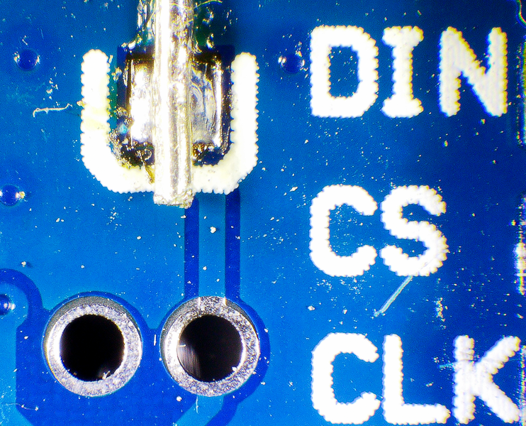
Warning
Electrolytic capacitors are polarized. Make sure to solder the positive side to the positive hole and the negative side to the negative hole.
In the photo below negative is on the left and positive is on the right. When in doubt, use a multimeter to confirm the orientation.