Configuring the output
Stepper motors are typically mapped to simulator variables that output numerical values. The following steps demonstrate how to use a 28BYJ-48 stepper motor with a ULN2003 driver to show the compass heading in Microsoft Flight Simulator 2020 and Microsoft Flight Simulator 2024.
Tip
The steps for using a stepper motor with X-Plane are similar. Use the X-Plane DataRef type when configuring the Sim Variable tab.
Create a new row in the outputs tab of the main window
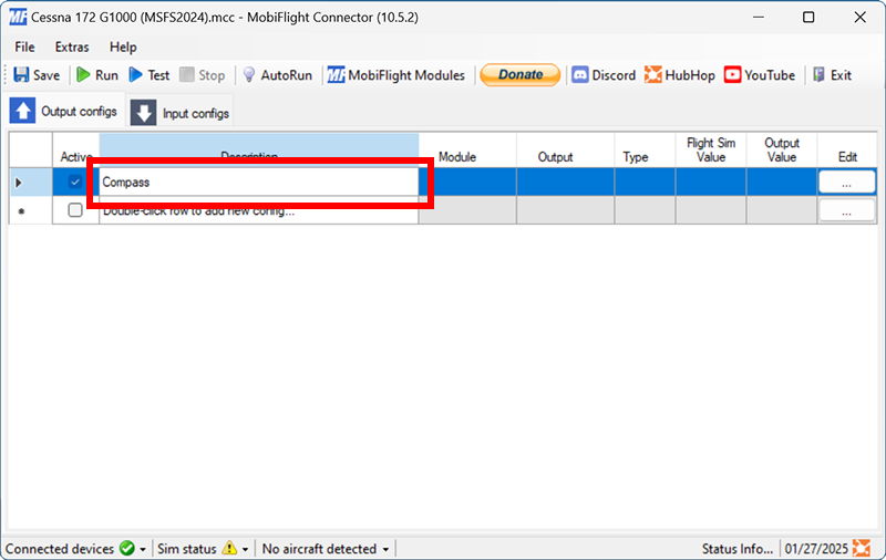
Double-click on the bottom row where the description says Double-click row to add new config… and enter a description for the output. For example, enter Compass for a stepper motor that will show the compass heading.
Open the output configuration dialog
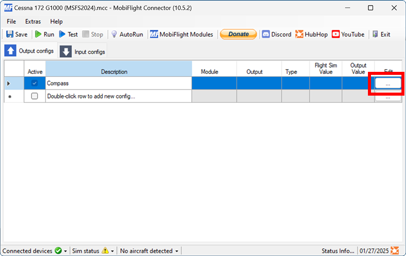
Click the button with three dots in the Edit column for the row created in the previous step.
Filter the output presets
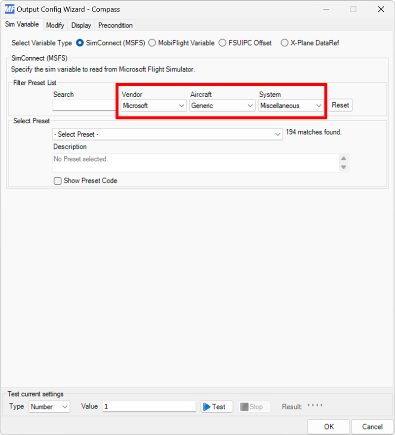
On the Sim Variable tab, use the Filter Preset List dropdowns to filter by Microsoft, Generic, and Miscellaneous.
Select the magnetic compass preset
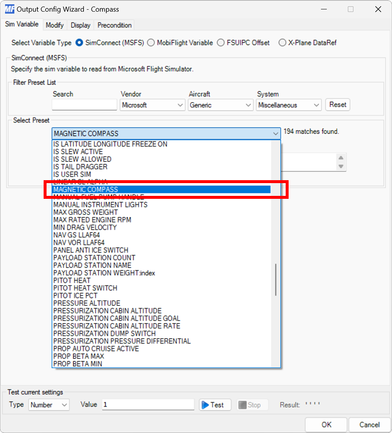
Use the Select Preset dropdown to select the MAGNETIC COMPASS preset.
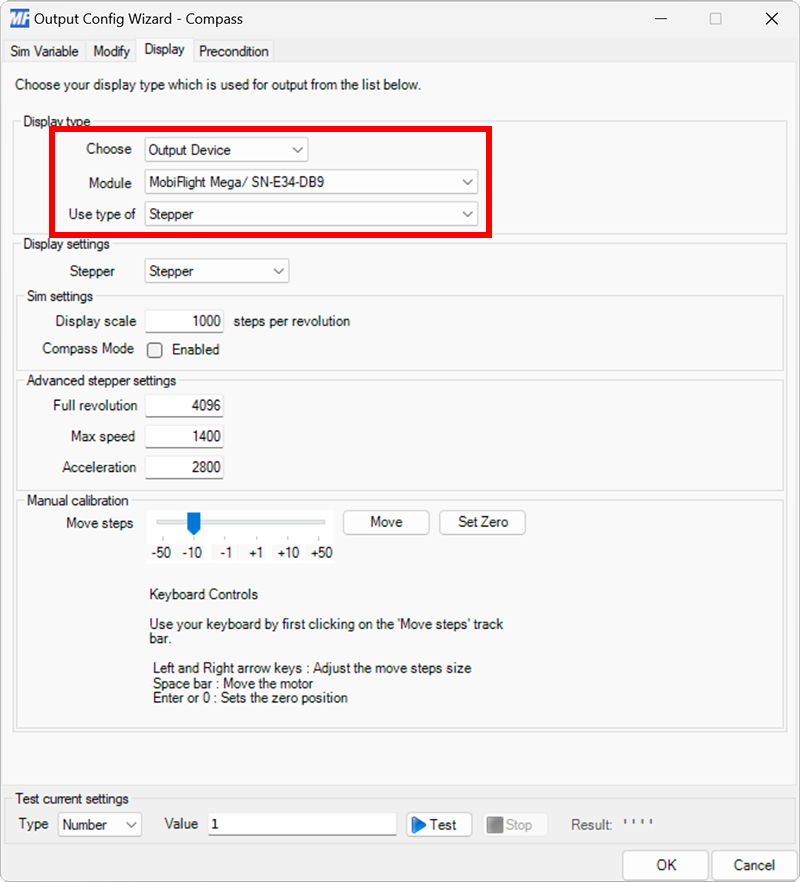
Select the board and device type for the output
On the Display tab, use the Module and Use type of dropdowns to select your connected board and the Display Module device type.
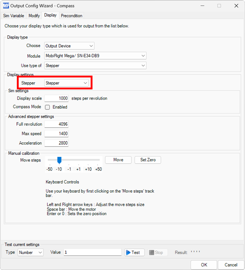
Select the stepper motor to use for display
Use the Stepper dropdown to select the stepper motor that should display the output value.
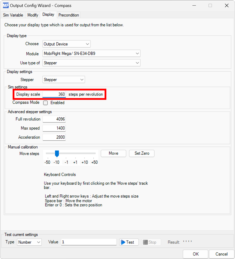
Specify the display scale
Since compass values are from 0–360, set the Display scale to 360 steps per revolution.
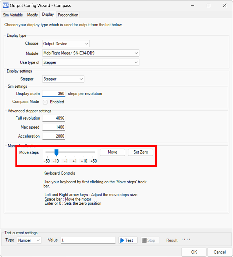
Set the stepper zero position
The zero position is the position MobiFlight will reset the stepper motor to when the connection to the simulator is lost.
To set the zero position, use the Move steps slider and Move button to rotate the stepper motor to the appropriate zero position, then click the Set Zero button to save the location.
Close the dialog and try it out
Click the OK button to close the dialog, then spawn an airplane in Microsoft Flight Simulator.
Make sure the MobiFlight Run button is clicked in the toolbar. The stepper motor should move to match the compass heading in the simulator.